
Post-Reflow SMT Automation: Complete Process Guide for 2026
1. Why Automate Post-Reflow Processes?
After a PCBA exits the reflow oven at 220–260°C, the work is far from over. The board must be cooled, inspected, depaneled, tested, aged, and packaged before it can be shipped. Traditionally, many of these steps were done manually by operators sitting at benches. But manual post-reflow handling has serious drawbacks:
- Inconsistent quality: Human inspectors miss 15–30% of visible defects, even with training
- High labor cost: 3–6 operators per line for inspection, testing, and handling
- Slow throughput: Manual handling becomes the bottleneck as mounter speeds increase
- ESD and handling damage: Every manual touch is an opportunity for ESD events or mechanical damage
- Poor traceability: Manual data entry is error-prone and difficult to audit
Post-reflow SMT automation solves all of these problems by creating a continuous, machine-paced flow from oven exit to packaged product. As component sizes shrink and quality requirements tighten in 2026, automated post-reflow lines are no longer a luxury—they are a competitive necessity.
2. The 7-Station Post-Reflow Process: Station by Station
A modern post-reflow SMT automation line typically includes seven core stations. The exact configuration depends on your product mix and quality requirements, but this 7-station layout is the industry standard for medium- to high-volume electronics manufacturing.
1Cooling Station
Boards exit the reflow oven at 150–180°C—far too hot for downstream equipment. The cooling station brings the board down to a safe handling temperature (typically <45°C) before it proceeds to inspection and testing.
Equipment options:
- Natural cooling conveyor — simple, low cost, but slow and space-intensive
- Forced-air cooling tunnel — faster, more compact, ideal for medium-to-high volume
- Water-cooled plate cooling — fastest option for high-power or thick boards
Selection tip: Match cooling capacity to your oven throughput. A 10-zone reflow oven at 1.2 m/min needs roughly 3–5 meters of forced-air cooling to bring boards below 45°C.
2AOI (Automated Optical Inspection)
AOI is the primary post-reflow quality gate. It uses high-resolution cameras and AI-based image processing to detect solder joint defects such as bridges, tombstones, missing components, insufficient solder, and polarity errors.
Equipment options:
- 2D AOI — basic inspection for simple boards, lower cost
- 3D AOI — height measurement capability for detecting lifted leads, coplanarity issues, and BGA solder volume
- Inline vs. standalone — inline models integrate directly with the conveyor; standalone requires board handling
Key specs to compare: camera resolution (typically 5–25 MP), FOV size, inspection speed (boards/hour), false call rate, and AI algorithm maturity.
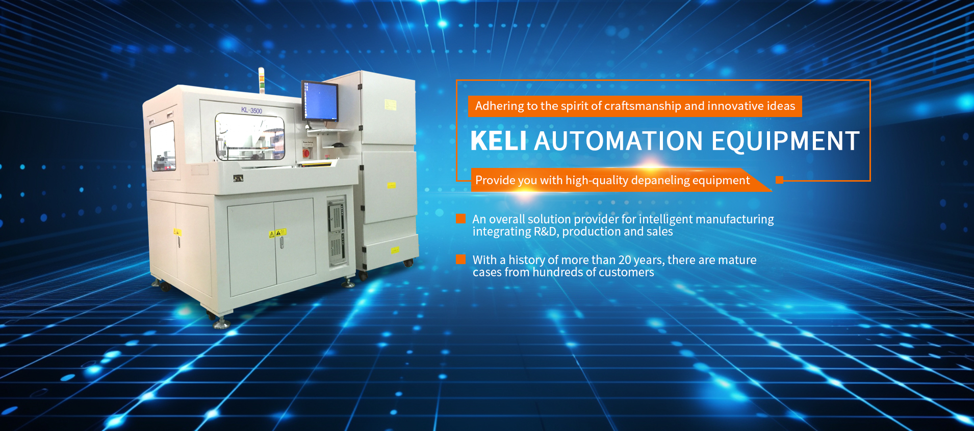
3Depaneling / Board Separation Station
Most PCBs are manufactured in arrays or panels (multipanels) to improve SMT line efficiency. After soldering and AOI, the individual boards must be separated. This is the depaneling station.
Equipment options:
- V-groove depaneling — fast, low cost, for boards with straight V-cut lines
- Router / curve depaneling — for complex board shapes, lower stress than punching
- Laser depaneling — non-contact, zero mechanical stress, ideal for fragile or high-density boards
- Punch depaneling — very fast, but high stress and dedicated tooling per board design
Selection tip: Consider board thickness, component proximity to edges, dust collection requirements, and changeover time between products.
4ICT (In-Circuit Test) Station
ICT verifies component-level integrity by measuring resistance, capacitance, diode polarity, and net continuity at hundreds of test points. It catches defects that AOI cannot see, such as internal component failures or hidden solder joint issues under BGAs.
Equipment options:
- Bed-of-nails ICT fixture with flying probe or fixed-pin architecture
- Inline conveyorized ICT for high-volume lines
- Standalone bench ICT for low-volume / high-mix production
Integration note: Keli's inline ICT stations integrate with MES systems to log serial-number-level test data and automatically route failed boards to rework.
5FCT (Functional Circuit Test) Station
FCT is the final functional verification: does the board actually work? The FCT station loads firmware, applies power, injects test signals, and measures outputs to confirm that the PCBA meets all functional specifications.
Equipment options:
- Semi-automated pneumatic FCT — operator loads board, fixture clamps automatically
- Fully automated inline FCT — conveyor-fed, robotic loading, fully automated test sequence
- Combined ICT + FCT — single fixture that performs both tests to save floor space and handling
FCT is often the most complex station because it requires custom test software, instrument integration, and product-specific fixtures—but it is also the most critical for ensuring end-customer quality.
6Aging / Burn-In Station
Aging (or burn-in) testing subjects boards to elevated temperature and voltage for an extended period to accelerate early-life failures. This is especially important for high-reliability products in automotive, medical, aerospace, and industrial applications.
Equipment options:
- Temperature-controlled aging racks with power cycling
- Environmental chambers with humidity and temperature cycling
- High-voltage stress test (hipot) combined with aging
Aging time varies by industry standard—typically 1–4 hours for consumer products, 24–100+ hours for automotive and aerospace.
7Packaging Station
The final station packages finished, tested boards for shipment. In a fully automated line, this may include:
- Labeling and serial number marking (laser or inkjet)
- ESD bag or tray packaging
- Carton sealing and palletizing
- Final weight and barcode verification
While often considered an afterthought, the packaging station is where traceability data is finalized and shipping errors are prevented. Integration with your ERP/WMS system is critical.
3. Equipment Selection by Production Volume
Not every line needs all seven stations, and not every station requires the highest-spec equipment. The right configuration depends on your production volume, product complexity, and quality requirements:
| Station | Low Volume (<5k/mo) | Medium Volume (5k–30k/mo) | High Volume (>30k/mo) |
|---|---|---|---|
| Cooling | Natural / bench fan | Forced-air tunnel | Forced-air + water-cooled |
| AOI | 2D standalone | 3D inline | Dual-lane 3D AOI |
| Depaneling | Manual / V-groove | Inline router | Dual-lane laser depaneling |
| ICT | Standalone bench | Inline bed-of-nails | Dual-stage inline ICT |
| FCT | Manual quick-clamp | Pneumatic semi-auto | Fully automated inline FCT |
| Aging | Benchtop oven | Rack-based aging | Continuous aging tunnel |
| Packaging | Manual | Semi-auto labeler | Fully automated packaging line |
4. Post-Reflow Line Planning: Key Considerations
Designing a post-reflow automation line is more complex than just stringing machines together. Here are the critical engineering factors to get right:
4.1 Throughput Matching (Takt Time)
The slowest station determines overall line throughput. Before finalizing equipment selection, calculate the cycle time of each station and ensure they are balanced to within 10–15% of each other. A common mistake is investing in a high-speed mounter only to have the line bottleneck at the FCT station.
4.2 Conveyor and Handling Design
- Board handling: Edge-rail vs. belt vs. palletized handling depends on board size, weight, and bottom-side component clearance
- Width adjustment: Motorized width adjustment is essential for high-mix lines
- Buffering: Add buffer conveyors between stations to absorb minor cycle time variations and prevent line stoppages
- ESD protection: All handling surfaces must be ESD-safe, with continuous grounding monitoring
4.3 Rework and Routing Strategy
Failed boards from AOI, ICT, and FCT need to be routed to rework. Options include:
- Dedicated rework conveyor branches
- NG (No Good) buffer conveyors for manual removal
- Automatic sorting and routing based on defect type
Plan rework flow from day one—adding it later is much more expensive.
4.4 Software and Data Integration
A modern post-reflow line generates massive amounts of data. Ensure your equipment supports standard communication protocols (SECS/GEM, OPC UA, MQTT) and can integrate with your:
- MES (Manufacturing Execution System)
- SPC (Statistical Process Control) software
- Traceability system (serial number tracking)
- ERP system for order and inventory data
5. ROI Calculation for Post-Reflow Automation
ROI Calculation Framework
Use this formula to estimate payback period for post-reflow automation:
Payback Period (months) = Total Investment ÷ Monthly Savings
Total Investment includes: equipment cost, installation, integration, training, and initial spare parts.
Monthly Savings come from:
- Labor savings (operators eliminated × monthly cost per operator)
- Yield improvement (reduction in escape defects × cost per defect)
- Throughput gain (additional units produced × margin per unit)
- Reduced rework cost (fewer defects caught earlier × rework cost per unit)
Typical ROI Scenario
Consider a mid-size EMS factory currently running 3 SMT lines with manual post-reflow:
- Current labor: 12 operators (4 per line) at $600/month each = $7,200/month
- Defect escape rate: 1.5% with manual inspection
- Average defect cost: $15 per escaped unit
- Monthly production: 60,000 boards
- Current monthly defect cost: 60,000 × 1.5% × $15 = $13,500/month
After installing 3 post-reflow automation lines:
- Labor reduction: 12 → 4 operators = $4,800/month saved
- Defect reduction: 1.5% → 0.2% = $11,700/month saved
- Total monthly savings: $16,500
- Total investment: ~$280,000 (3 lines)
- Estimated payback: ~17 months
Your exact ROI will vary based on product type, labor costs, and defect rates, but payback periods of 12–24 months are typical for well-designed post-reflow automation projects.
6. Keli's Post-Reflow Automation Solutions
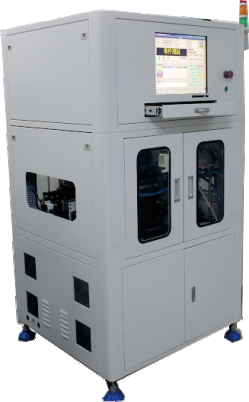
Keli Automation has been building post-reflow SMT automation lines since the early 2000s. Our approach is different from pure equipment vendors—we start with your process requirements and product mix, then design a complete turnkey solution from cooling to packaging.
Our post-reflow line capabilities include:
- Turnkey 7-station post-oven lines — fully integrated from cooling to final packaging
- Custom depaneling solutions — V-groove, router, laser, and punch options
- Inline ICT and FCT — with our own fixture design and manufacturing (30-year heritage)
- Aging and high-voltage test lines — for automotive and high-reliability products
- 3C industry automation — specialized solutions for consumer electronics assembly
- MES integration — full traceability and data collection with standard protocols
What makes Keli unique is our vertical integration. Unlike system integrators who buy everything from third parties, we design and manufacture our own fixtures, depaneling machines, test systems, and custom automation cells. This means faster delivery, better quality control, and single-source responsibility for the entire line.
We also offer flexible commercial models—from standard equipment to fully custom turnkey lines—backed by on-site installation, training, and 24/7 technical support.
Planning a Post-Reflow Automation Line?
Send us your production volume and product specs. Our SMT automation engineers will design a custom line layout and ROI analysis for your facility — free of charge.
Request Line Design & ROI